A 3D model is an essential geometry source for CNC planning, but it is not automatically a complete manufacturing specification. OEM buyers still need to define the controlled drawing revision, critical interfaces, datum hierarchy, incoming weldment condition, machining allowance, setup assumptions, tolerances and inspection requirements. In a heavy structural component, the supplier must convert digital geometry into a physical reference system that survives fabrication, fixturing, machining and measurement. A good 3d cnc machining plan therefore connects CAD data to manufacturing authority and final acceptance instead of treating the model as a self-explanatory production file.
A 3D Model Shows Geometry, Not the Complete Machining Intent
A CAD model can show surfaces, holes, bores, bosses, ribs and assembly features with excellent geometric clarity. What it may not show clearly is which of those features matter most to the machine assembly or which dimensions should control the manufacturing sequence.
For CNC machining from 3D model data, the supplier still needs answers to several questions:
- Which file revision is released for production?
- Which surfaces are function-critical?
- What datum system controls those features?
- Which tolerances are authoritative?
- What condition will the part be in before machining begins?
- How should inspection reproduce the same reference system?
Without these decisions, two suppliers can import the same model and create different setup plans that are both geometrically plausible but not equally suitable for the OEM’s assembly requirements.
Critical Interfaces Should Be Identified Before CAM Programming
Heavy machinery structures contain many surfaces that are visually prominent but not equally important. The features that deserve early attention are the ones that control how the finished component connects to the rest of the machine.
Typical examples can include:
- mounting faces;
- bearing or slewing interfaces;
- pin bores and lug relationships;
- bolt-hole patterns;
- support pads;
- mating edges and connection surfaces.
For CNC machining complex 3D parts, these interfaces should be marked in the technical package before the supplier chooses toolpaths. Otherwise, programming effort can be optimized around geometry that has low functional risk while the true assembly relationships receive too little control.
This is especially important in welded structures because the final machining stage may be the point where functional relationships are established or corrected after fabrication.
The Datum Strategy Converts CAD Geometry Into a Physical Process
A 3D model for CNC machining exists in a digital coordinate system. The physical workpiece needs a corresponding manufacturing reference system that can be located on the actual part.
The datum plan answers:
- Where is part zero established?
- Which physical surface or feature represents that reference?
- How is the workpiece oriented to the machine coordinate system?
- Which later setups can recover the same reference?
- How will inspection use the same or a clearly related datum structure?
CAM software typically requires a work coordinate system, stock definition, model orientation and fixture context before toolpaths are created. For the buyer, that software workflow reflects a broader manufacturing principle: the model must be tied to a real stock condition and a measurable physical reference.
A weak datum scheme can cause a part to meet isolated dimensions while missing the relationship among critical interfaces.
Why the Finished 3D Model Does Not Define Machining Allowance
The final CAD model normally represents the intended finished geometry. A welded structural component, however, reaches the machining stage in an earlier physical condition. Material may remain on selected surfaces so that final interfaces can be machined after fabrication. Welding and handling can also influence the as-fabricated condition.
Therefore, large part CNC machining from CAD requires an explicit link between:
finished geometry → incoming weldment condition → available machining stock → setup sequence → final geometry.
The buyer should not assume that a supplier can infer the correct machining allowance from the finished model alone. Where allowance is controlled by the OEM drawing or fabrication standard, it should be stated. Where the supplier is expected to propose it, that assumption should be visible in the quotation and later approved.
No generic allowance value should be copied from another project simply because the components look similar.
3D CNC Machining Still Requires Setup and Accessibility Planning
The term 3d cnc machining sometimes creates the impression that a 3D model can be loaded into CAM software and machined as one uninterrupted operation. Physical manufacturing is more constrained.
Each setup has to define:
- how the part is supported;
- where the fixture can contact the structure;
- which areas are accessible to the cutter;
- which features can be reached in the current orientation;
- how the workpiece can be lifted or repositioned;
- which reference remains available for the next setup.
Even advanced 3D toolpaths depend on physical tool access. A surface that exists in the model may still be inaccessible because another plate, rib or fixture blocks the cutter. A long tool may technically reach the feature but create a less rigid process. These conditions need to be evaluated before the buyer accepts the machining route.
Which File Is Authoritative When 3D and 2D Data Differ?
A model-based workflow becomes risky when the 3D model, 2D drawing and written notes do not share a clear revision and authority structure.
The RFQ or purchase specification should state which document controls:
- nominal geometry;
- GD&T and tolerances;
- surface requirements;
- special process notes;
- inspection characteristics;
- approved deviations.
If the 3D model and drawing disagree, the supplier should not silently choose one. The discrepancy should be resolved before production and recorded against the controlled revision.
Document-control rule: a model-based process still needs revision control. “Use the latest CAD” is not a substitute for an identified released file and drawing revision.
How Should a Model-Based CNC Machining Plan Be Reviewed?
| Input | Manufacturing Question | Buyer Evidence |
| Controlled 3D model | What geometry is being manufactured? | Released file and revision |
| 2D drawing | Which tolerances and notes govern? | Approved drawing revision |
| Critical interfaces | Which features drive assembly fit? | Marked characteristics or inspection plan |
| Datum system | How are setups and measurement referenced? | Datum definition on drawing or agreed process plan |
| Incoming condition | What geometry reaches machining? | Fabrication/weldment definition |
| Machining allowance | What stock is available for final machining? | Drawing requirement or approved supplier proposal |
| Setup plan | How many orientations and datum transfers are expected? | Supplier process concept |
| Inspection scope | How is conformity proven? | Dimensional results tied to the controlled references |
This review keeps the project focused on manufacturing intent rather than software screenshots.
How Does an Excavator Upper Frame Fit the Model-Based Planning Problem?
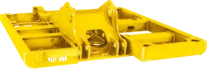
WLD lists the Excavator Upper Frame Slewing Platform within its construction-machinery product range. The current product description emphasizes welding quality and precision fabrication for stability under complex working conditions.
The supplied product information does not publish a dedicated “3D CNC machining service” or a machine-axis specification for this component. It does, however, provide an appropriate structural context for model-based planning: an OEM structure must be manufactured from controlled geometry and then fit the machine assembly for which it was designed.
For that kind of project, the 3D model should therefore be treated as one element in a larger manufacturing package that includes fabrication definition, functional interfaces and inspection criteria.
OEM buyers can review WLD’s broader machinery structural component range when deciding which product geometry and project documents should accompany an RFQ.
How Should the Supplier Prove the Machined Result Matches the Model?
The final inspection plan should reproduce the functional logic of the design. A report listing dimensions without reference to the correct datums may not prove that the structure will assemble correctly.
For model based CNC machining, useful acceptance evidence can include:
- drawing/model revision identification;
- measurement of critical mounting or connection interfaces;
- datum-based positional checks;
- first-article results for a new or revised design;
- documented deviations and approvals;
- traceability between the measured part and the released project definition.
The exact measurement method depends on the part, tolerance and project specification. The buyer’s goal is not to request the largest possible report; it is to prove the dimensions that control assembly and function.
What Should Go Into a 3D CAD CNC Machining RFQ?
A complete RFQ should make the digital model manufacturable rather than merely viewable.
- Provide the released 3D model and 2D drawing.
- Identify the governing revision.
- Mark critical assembly interfaces.
- Define the datum system and tolerance authority.
- State the incoming fabricated or welded condition.
- Define machining allowance where the OEM controls it.
- Identify inaccessible or restricted clamping areas.
- State required first-article and inspection evidence.
- Provide batch quantity and repeat-production expectations.
- Require the supplier to declare assumptions or deviations before order release.
That package supports a stronger 3D CNC machining process because it gives the supplier enough information to plan setup, stock, tool access, datum transfer and inspection coherently.
For an OEM structural-component project, send the controlled CAD package and manufacturing requirements through WLD’s Contact / RFQ page. The most useful supplier response is not “we can machine from 3D.” It is a clear explanation of how the released model will be converted into setups, datums and measurable acceptance criteria for the actual welded structure.