3-axis CNC machining can be sufficient for a heavy welded part when the critical machined features are accessible from a practical set of fixed orientations and the datum relationships can be preserved through each setup. Axis count alone does not answer the sourcing question. OEM buyers need to review which faces must be machined, how the weldment will be supported and repositioned, whether the cutter can reach every functional feature, how datums are transferred, and how final interfaces will be inspected. For large machinery structures, a stable process plan can matter more than choosing the highest-axis-count machine.
What Can 3-Axis CNC Machining Handle Well?
In a conventional 3-axis milling arrangement, tool motion is programmed along the X, Y and Z directions while the workpiece remains fixed in one orientation during a setup. That makes the process well suited to many planar and directly accessible features, including mounting pads, flat faces, bolt-hole patterns, pockets, bores and other features that can be reached from the active tool direction.
For 3 axis CNC machining for large parts, however, the important question is not whether a feature can be cut in isolation. The buyer needs to know whether the entire set of function-critical features can be produced in a controlled sequence without creating excessive repositioning or losing the relationship between reference surfaces.
A large welded structure may therefore be a good candidate for 3-axis machining even when its overall geometry is complex, provided the machining scope is concentrated on accessible interfaces. Conversely, a visually simple structure can become difficult if important features sit on several opposing or angled faces.
Buyer decision: evaluate feature accessibility, setup count and datum continuity together. “Three axes” describes machine motion; it does not define the complete manufacturing route.
Part Geometry Matters More Than the Axis Number
A heavy machinery component often combines welded plates, ribs, brackets, mounting seats and machined interfaces. From the procurement side, those interfaces are not equally important. Some simply create clearance. Others determine whether the structure mounts, aligns or connects correctly to another assembly.
The first review should identify:
- all finished machined faces;
- critical bores and hole patterns;
- interfaces that must stay in position relative to one another;
- features located on opposite or angled sides of the structure;
- areas where tool access is restricted by ribs, brackets or surrounding geometry;
- surfaces that will serve as manufacturing or inspection datums.
Once these are marked, the buyer and supplier can decide whether a 3 axis machining heavy welded parts route is straightforward or whether multiple orientations introduce too much process risk.
Multiple Setups Are Not Automatically a Problem
Large welded structures frequently require more than one setup. The problem is not the existence of multiple setups; it is whether each setup is connected to a controlled reference strategy.
A typical decision chain looks like this:
incoming weldment → establish primary reference → machine first interface group → reposition → recover datum → machine second interface group → inspect cross-setup relationships.
If that chain is defined and measurable, multiple setups can be a normal part of the process. If it is vague, the same repositioning can create accumulated location error, inconsistent batch results or assembly rework.
This is where a large part CNC machining setup should be evaluated as a process rather than as a machine specification. The RFQ should ask how the workpiece will be supported, how reference features survive repositioning, and which final dimensions cross setup boundaries.
Datum Transfer Is the Critical Control Point
For a large weldment, datum transfer often carries more procurement risk than the nominal axis count. A supplier may machine one face accurately, yet the finished assembly can still be wrong if the next setup is established from a weak or inconsistent reference.
The buyer should ask four questions:
- Which surfaces or features establish the primary manufacturing datum?
- Which datums remain available after the first machining operation?
- How is the part relocated after turning or repositioning?
- Which final inspection checks prove that features from different setups remain in the required relationship?
For CNC machining datum transfer, the useful evidence is not simply a statement that the machine is accurate. The supplier should be able to describe the reference chain from the approved drawing through setup and inspection.
When Does Tool Access Make the Process More Complex?
A 3-axis process is easiest when the tool can approach the required feature along a practical direction with adequate clearance. Complexity rises when the geometry creates deep recesses, obstructed faces, undercuts, angled interfaces or long tool reach.
Long reach can reduce rigidity. Obstructions can force the part into another orientation. Angled interfaces may require additional fixturing or a different machining strategy. For buyers, these conditions should trigger a review before the quotation is finalized.
| Part Condition | Buyer Question | Why It Matters |
| One main machined face | Can the critical features stay in one stable setup? | May reduce datum transfers and fixture changes. |
| Opposite critical faces | How will the second orientation recover the datum? | Cross-setup relationships may control assembly fit. |
| Several angled interfaces | Can the tool reach them without unstable positioning? | Access may change the machine or fixture plan. |
| Deep or obstructed feature | What tool reach and clearance are required? | Tool access can affect rigidity and machining sequence. |
| Large welded structure | What is the incoming weldment condition before machining? | Fabrication condition influences support, allowance and setup. |
| Critical hole pattern | How will position be measured from the controlled datum? | Individual hole size is not enough if pattern position drives fit. |
Does a 3D Part Automatically Need More Than 3-Axis Machining?
No. A three-dimensional CAD model does not automatically require simultaneous multi-axis cutting. Many 3D parts contain a combination of surfaces that can still be machined through standard 2.5-axis and 3-axis operations when the part is oriented appropriately.
This is why 3d cnc machining should not be treated as a synonym for a specific machine configuration. The process choice depends on feature accessibility, workholding, the number of practical setups, tolerance relationships and the required surface geometry.
For an OEM buyer, the more useful question is: “Can the supplier reach and control every critical interface with the proposed setup plan?” That question works whether the final route uses one setup, several 3-axis setups or another machining approach.
How Does an Excavator Lower Frame Illustrate the Decision?
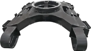
WLD lists the Excavator Lower Frame as a construction-machinery structural component. The current product description identifies the lower frame as a support structure for the unloading and walking system and notes that it is mainly welded from longitudinal beams, an X frame and a slewing-support mounting seat.
That product description does not state that WLD uses a particular 3-axis machine or that every lower frame follows the same CNC route. What it does show is why the process decision matters: a welded support structure combines geometry, load-bearing structure and assembly interfaces. For an OEM project, the machining plan should therefore be reviewed against the actual drawing rather than inferred from the product name.
Buyers can also review WLD’s broader Construction Machinery structural components to see the type of welded OEM products for which drawing-controlled interface machining can become part of the procurement discussion.
What About Buyers Searching in Minneapolis or Saint Paul?
Queries such as 3 axis cnc machining Minneapolis and 3 axis cnc machining Saint Paul MN usually express a local sourcing preference. That preference can be reasonable for small urgent jobs, service work or projects where face-to-face access dominates the decision. It should not automatically decide a heavy OEM weldment project.
WLD is not presented in the supplied company data as a Minneapolis or Saint Paul local CNC shop. Its documented position is an OEM structural-component manufacturer serving global machinery and industrial projects. For buyers comparing a local machining source with an overseas structural-component supplier, the evaluation should therefore focus on project fit rather than location labels.
Useful comparison points include:
- maximum practical part envelope and handling plan;
- welded-structure manufacturing experience;
- drawing and revision control;
- setup and datum strategy;
- inspection of cross-setup interfaces;
- repeat-batch capability;
- packaging and logistics for the finished structure.
The geographic search term can start the supplier search, but the approved supplier should be the one that can control the actual component definition.
What Should the RFQ Include Before a Supplier Confirms the Machining Route?
A useful RFQ for CNC machining welded structures should allow the supplier to judge the process without guessing at the critical geometry.
- controlled 2D drawing and 3D model where available;
- finished part envelope and mass;
- incoming fabricated or welded condition;
- critical machined faces and bores;
- datum scheme;
- tolerances that cross setup boundaries;
- machining allowance where defined by the project;
- lifting and clamping restrictions;
- inspection and first-article requirements;
- batch quantity and repeat-order expectations.
The supplier response should then identify the proposed machining sequence, important setup assumptions, any required deviations and the inspection approach for function-critical interfaces. This makes it possible to compare process routes rather than compare machine-axis labels.
For a drawing-based project, use WLD’s Contact / RFQ page to send the structural-component definition and machining requirements. The decision should be based on whether the proposed route can control the part—not on whether “3-axis” sounds simpler or “multi-axis” sounds more advanced.