



Steel Plate Cutting
Plasma or flame cutting may be selected according to the material, thickness, profile and drawing requirements. Confirm cut geometry, edge condition and any allowance required by subsequent operations.

+86 0516 85628519

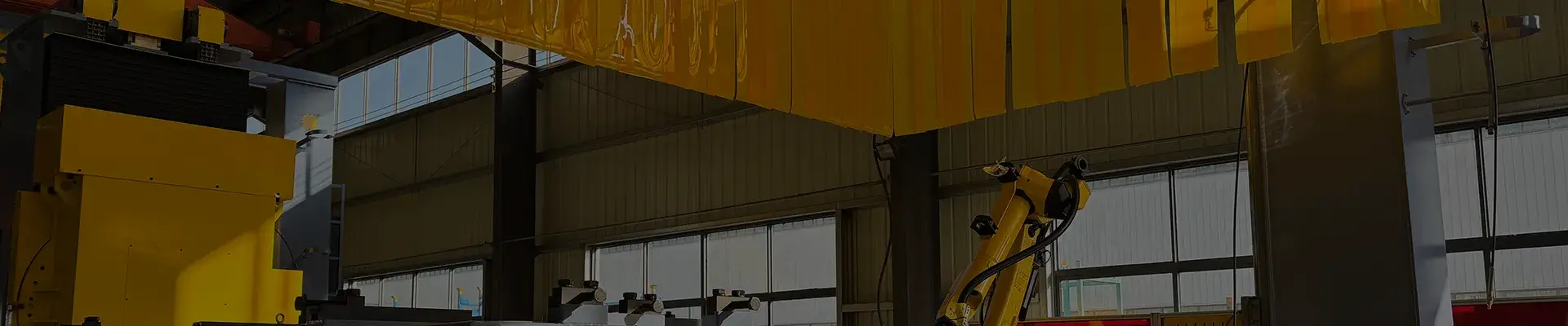
A plate component may be supplied as a cut blank, a formed part, a welded subassembly or part of a complete machinery structure. The enquiry should make clear which condition is required.
For a heavy equipment project, the drawing defines more than the plate outline. It may also identify material requirements, openings, formed edges, joining details and interfaces that connect the component to other assemblies. These requirements influence how cutting, forming, welding and machining are coordinated.
WLD’s published manufacturing capabilities include plasma and flame cutting, bending, welding, CNC machining and painting. The specific combination of processes should be confirmed for each component rather than assumed from a general capability list.
Each process answers a different manufacturing requirement. The drawing and agreed scope determine which operations are needed.
Plasma or flame cutting may be selected according to the material, thickness, profile and drawing requirements. Confirm cut geometry, edge condition and any allowance required by subsequent operations.
Formed plate components require clear information about bend locations, angles, dimensions and their relationship to adjoining parts. The forming sequence should be considered alongside later assembly requirements.
Where plate parts become a welded structure, define joint locations, drawing revisions and any specified weld or inspection requirements. The supply scope should identify whether WLD is being asked for an individual part or an assembly.
Some fabricated components include mounting faces, bores, holes or other interfaces that require machining. Identify these features and their datums on the drawing; the applicable machining route must be reviewed for the actual workpiece and equipment.
State the required finish, surfaces to be protected and any areas that must remain uncoated. Packaging and transport protection should be defined for exposed machined interfaces where relevant.
Agree which dimensions, interfaces, welds, material records or coating characteristics require inspection, and what records are expected at delivery.
The sequence below illustrates how operations may be coordinated. Not every project requires every stage, and the actual route depends on the component design and agreed order scope.
Confirm the drawing revision, material specification, plate dimensions and required supply condition.
Define the profile, openings, edge requirements and any allowance needed for later work.
Review bend locations, angles and dimensions in relation to the component geometry.
Where required, coordinate plate parts into a welded component according to the approved drawings.
Identify the interfaces that require machining and the datums used to define them.
Complete the agreed checks, painting, protection and dispatch preparation.
The following WLD products provide examples of machinery structures and components. They are product references, not claims that every item follows an identical plate-processing route.
A load-bearing body for mining truck material transport. Project drawings should define the body structure, material requirements, interfaces, finish and delivery condition.
View product details →WLD describes this welded structure as comprising longitudinal beams, an X frame and a slewing-support mounting seat. These connected elements make the drawing and interface requirements important to the supply scope.
View product details →A frame for mobile crushing equipment. Define the required structure, machining areas, coating requirements and dispatch conditions for the specific project.
View product details →WLD lists excavator buckets for digging and material-handling applications. The component drawing should establish the required geometry, material and wear-related specifications.
View product details →A useful steel plate machining enquiry connects the material, geometry and required finished features to one controlled drawing package.
Identify the specified steel grade and material standard, plate thickness, dimensions and any required material documentation. If alternatives may be considered, state who must approve them. Do not rely on a generic description such as “carbon steel” when the drawing calls for a defined grade.
Mark the plate profile, openings, slots, bevels and formed features. Include bend angles and dimensions where applicable, and identify relationships that affect fit with adjoining components.
Identify the faces, bores, holes or connection interfaces that require machining. Show relevant datums, critical dimensions and acceptance requirements. Distinguish machined surfaces from adjacent as-cut, formed or welded surfaces.
Specify the paint system or finish required by the project, areas to mask or protect, packaging expectations and transport constraints. Note any machined interfaces that need protection before dispatch.
Inspection should follow the characteristics and acceptance criteria defined for the order. A single generic inspection statement is not a substitute for an agreed inspection scope.
| Inspection area | What should be defined | Buyer-side information |
|---|---|---|
| Dimensional inspection | Specified dimensions, positions, datums and interfaces to be checked. | Controlled drawing, critical-feature identification and acceptance criteria. |
| Welding inspection | Applicable welds, inspection method and any required records. | Welding requirements and agreed inspection scope. |
| Material and thickness | Material identity and plate thickness checks where required. | Material specification and required certificates or records. |
| Coating inspection | Specified finish and coating characteristics to be verified. | Finish requirements, areas to mask and acceptance criteria. |
WLD’s company information describes inspection equipment including portable coordinate measuring equipment, thickness gauges, magnetic-particle and ultrasonic testing equipment, hardness testing and coating-related instruments. The inspection method and equipment used for a particular order should be confirmed against the required characteristics; this page does not imply that every method is applied to every component.
WLD’s published company information states a maximum steel plate processing thickness of 120 mm. The applicable material, process, dimensions and drawing requirements should be reviewed for each project. This figure should not be interpreted as a universal thickness limit for every machining operation.
WLD describes plasma cutting, flame cutting, bending, welding, CNC machining and painting among its manufacturing capabilities. The processes included in a particular order depend on the component and the agreed supply scope.
The required scope can be discussed as part of a custom component enquiry. Provide the drawing and identify which areas require cutting, forming, welding or machining so the manufacturing route can be reviewed.
Provide the latest drawing revision, material grade and standard, plate thickness and dimensions, required machining features, order quantity, finish and inspection requirements. Clarify whether the requested supply is a plate part, a welded subassembly or a finished structural component.
WLD lists painting among its manufacturing capabilities. Specify the required finish, surfaces to be masked, protection for machined interfaces and any project-specific acceptance criteria for review.
Identify each machined face, bore, hole or interface with clear dimensions and datums. Use detail views where necessary and distinguish machined features from cut, formed or welded surfaces.
Share your drawings, material requirements, plate thickness, machining details, expected quantities and finishing requirements with WLD. The manufacturing scope can then be reviewed against the actual component and project specifications.
Request a Quote


