How to Write CNC Machining Drawings with GD&T and Tolerances That Suppliers Can Quote Accurately matters because readers need a clear, practical answer to CNC Machining. This article breaks the topic into Prerequisites Before Drafting a CNC Drawing, Set a Default General-Tolerance Block Before Adding Any GD&T, Apply Design-for-CNC Limits Before Submitting the Part so the reader can move from understanding to decision-making without fluff.
Prerequisites Before Drafting a CNC Drawing
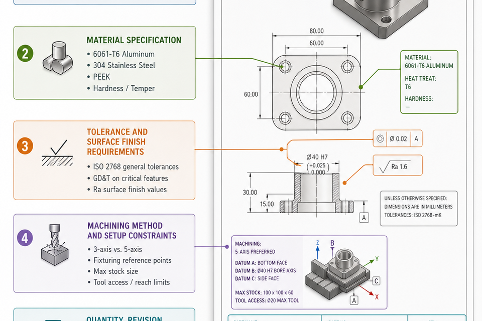
Define these five inputs before drawing a single line. Each one maps to a specific callout on the finished drawing, and missing any of them is the most common cause of quoting delays and rework with CNC shops.
Most inflated or inconsistent CNC quotes start with the drawing, not the shop. Blanket tight tolerances force shops to price every feature as a precision feature. Fix the drawing first, then compare quotes.
Step 1: Define function before dimensions.
- What: List mating fits, sealing faces, and load paths for each part.
- Why: Only these features justify tight control.
- How: Mark each feature as critical or standard in your notes.
Step 2: Set a default tolerance block.
- What: Reference a standard such as ISO 2768-m in the title block.
- Why: Every unlabeled dimension gets a known, routine tolerance.
- How: Add the block once, then leave standard features alone.
Step 3: Reserve GD&T for critical features.
- What: Apply ASME Y14.5-2018 callouts to bearing bores and mating surfaces only.
- Why: Each callout adds inspection time, which shops price in.
- How: Write the inspection method beside each callout, such as CMM or bore gauge.
Example: A pump housing has a Ø25 H7 bearing bore and a flange face held to 0.05 mm flatness. Everything else uses ISO 2768-m. The supplier sees exactly which two features drive inspection.
Step 4: Gather inputs and assign roles.
- Collect annual volume, target material, and surface finish needs.
- Assign one design owner, one manufacturing or quality reviewer, and one buyer to own the RFQ.
Budget time: Plan 1 to 2 days to draft and review one drawing. Then allow 1 to 2 weeks to gather quotes from 3 to 5 shops.
Common mistake: Tightening tolerances “to be safe.” This adds cost to every feature and hides the few dimensions that matter.
Pro tip: Compare quotes line by line. If one shop’s price stands out, check which features it treated as tight.
Editor note: Validate any cost multiplier used in this section against your own shop quotes before publication.
Ready to check your RFQ package before you send it? Send your drawing for review.
Set a Default General-Tolerance Block Before Adding Any GD&T
Add a general-tolerance note to the title block, and every dimension without its own tolerance inherits it. For most machined parts, ISO 2768-m (medium) is the right starting class. Reserve explicit tolerances for the few features that control fit or function.
Why it matters: An unspecified dimension falls back to the shop’s standard tolerance. Shops plan fixtures and inspection around that standard, so they quote it faster and cheaper than a blanket tight tolerance.
How to set it up (about 30 minutes, plus one review):
- Pick the class. Write “ISO 2768-m” in the title block. Use -f only where non-functional dimensions still need closer control.
- Add geometric defaults if your standard requires them. ISO 2768-2 covers straightness, flatness, angularity, and symmetry with classes H, K, and L. Set these defaults once in the block, not feature by feature.
- State the scope. Write “Unless otherwise specified, all non-toleranced dimensions per ISO 2768-m.” Vague scope causes most quote questions.
- Assign explicit tolerances to functional features only. Bearing bores, mating faces, and datums get GD&T callouts. Everything else stays on the default.
- Review the block with the shop’s inspection lead before release. Ask which default class their gauges and CMM routines already support.
Example: A housing has 40 dimensions. Four are functional: two bores, a mating face, and a hole pattern. The other 36 take the default, so the shop inspects four features to a tight standard.
Common mistake: Copying a tight tolerance across the whole part “to be safe.” Every feature then moves into the high-cost tier, and the shop checks all 40 dimensions to a tighter standard.
Cost drivers and the drawing decisions behind them:
| Cost driver | Drawing decision that moves it |
| Setup time | Number of orientations and datum schemes |
| Machine hourly rate | Tightest tolerance, which sets machine class |
| Material and stock waste | Stock size needed for datum and finish allowances |
| Batch size | Quantity spreading the setup cost |
Illustrative model (placeholder numbers, not market prices): Assume $800 total setup, $80/hour machine rate, 10-minute cycle, and $6 material per piece.
- 50 pieces: Setup adds $16 per part. Total per part is about $35.33, and setup is roughly 45% of it.
- 5,000 pieces: Setup adds $0.16 per part. Total per part is about $19.49, and setup is under 1%.
A tolerance change that adds 20% to cycle time adds $2.67 per part. On the 5,000-piece run, that is about $13,333.
Apply Design-for-CNC Limits Before Submitting the Part
The fastest way to avoid a rejected RFQ is to check every feature against what a cutter can physically reach before the drawing leaves your desk. A feature that breaks tool geometry forces a secondary operation, special tooling, or a re-quote. This check takes less time than the back-and-forth it prevents.
Note that this section uses machining geometry, not benchmark results. The quote-variance test across shops is not yet complete, so no outcomes from it appear here.
Step 1: Check internal corners
What: Confirm every internal corner has a radius.
Why: A round cutter cannot produce a sharp internal corner. Sharp corners need EDM or hand finishing, which adds cost and time.
How: Match the radius to a standard end mill. A cutter of radius r can produce a corner no tighter than r. A 1/4-inch (6.35 mm) end mill leaves at least a 3.175 mm (1/8-inch) corner radius. Call that out on the drawing.
Common mistake: Drawing sharp internal corners on pockets, then adding tight corner tolerances. The corner cannot hold the callout the drawing asks for.
Step 2: Check pocket depth against width
What: Compare pocket depth to the narrowest opening you cut into.
Why: Deep, narrow pockets need long tools. Long tools deflect, chatter, and cut less accurately.
How: Ask your shop for its maximum depth-to-width ratio at the tool length you need. Widen the pocket or reduce depth where the ratio is tight.
Step 3: Check wall and web thickness
What: Confirm thin walls and webs survive machining and handling.
Why: Thin features vibrate during cutting and can distort after clamping or stress relief.
How: Ask the shop for its minimum wall thickness for your material. Add a note on the drawing if the feature needs a minimum.
Step 4: Check hole depth ratios
What: Compare hole depth to diameter.
Why: Deep holes need special drills or peck cycles, which slow cycle time and raise cost.
How: Use standard drill sizes where possible. If you need a deep hole, confirm the shop’s depth limit first.
Step 5: Specify standard tool sizes
What: Choose dimensions that match standard cutters and drills.
Why: Standard tooling is in stock and fast to load. Odd sizes often need custom tools.
How: Round hole diameters and pocket radii to standard drill and end mill sizes. Call out a non-standard size only when the part needs it.
Pro tip: keep a shared capability sheet
Build a one-page sheet with each shop you use. List its minimum corner radius, depth limits, wall minimums, and standard tool sizes. Update the sheet after every quote cycle, when you learn which limits a shop actually enforces. Capability varies by machine, so the sheet becomes your fastest reference.
Time estimate: For a moderately complex part with about 20 features, expect roughly 30 to 60 minutes for the full check. That time is far less than a re-quote cycle.
If you want to compare shop capabilities before you submit, contact our team to talk through your part geometry.
Tie Tight GD&T Callouts to Functional Features Only
Put tight GD&T callouts only on bearing bores, mating faces, and datum features. Give everything else a general tolerance. Write the inspection method beside each callout so the shop can price it.
Some teams add tight callouts to every feature to be safe. That approach costs more. Each extra callout adds setup, fixturing, and CMM time to every part in the run.
Step 1: Sort features into tiers
- What: Tier 1 is functional (bores, mating faces, datums). Tier 2 is a size-only fit. Tier 3 is everything else, such as pockets and clearance holes.
- Why: Only Tier 1 controls how the part mates, locates, or rotates.
- How: Ask whether a feature touches another part, carries a load, or sets a reference. If not, it’s Tier 3.
Step 2: Apply the matching callout
- What: For a bearing bore, call out diameter, cylindricity, and position to datums. For a mating face, call out flatness and perpendicularity to a datum.
- Why: These callouts define fit. Tight limits elsewhere add cost without improving function.
- How: Keep Tier 3 features on the general tolerance block (for example, ISO 2768-m).
Step 3: Note the inspection method
- What: Write “CMM” or “go/no-go gauge” next to each callout.
- Why: A shop that sees “CMM, 100%” prices the inspection. A shop that sees nothing assumes the worst.
- How: Mark each callout as 100% or sampled.
Step 4: Define internal radii and wall minimums
- What: State the internal corner radius and minimum wall thickness.
- Why: An unspecified radius lets each shop choose its own tooling and process.
Hypothetical RFQ example
A hypothetical aluminum housing has a Ø30 bearing bore, a mating face, and four internal pockets. The drawing lists datum A only. It gives no radius for pocket corners.
Three hypothetical shops quote three different parts:
- Shop 1 assumes sharp internal corners and quotes a secondary operation.
- Shop 2 assumes a small radius and quotes standard end mills.
- Shop 3 assumes a larger radius and quotes a different tool set.
The buyer cannot compare these quotes. The fix is a clear datum frame and explicit allowances.
Revised drawing (hypothetical values)
- Datum A: mating face. Datum B: bore axis. Datum C: side face.
- Ø30 H7 bore: cylindricity 0.01 mm, position 0.05 mm to A|B, CMM 100%.
- Mating face: flatness 0.02 mm, CMM sampled.
- Pocket corners: R0.8 min. [Verify against supplier’s published capability sheet.]
- Wall thickness: 1.5 min. [Verify against supplier’s published capability sheet.]
Supplier question sheet
- Which tool diameter sets the minimum internal radius?
- What minimum wall thickness do you hold on pockets this depth?
- Which callouts do you inspect at 100%?
- Does your quote include CMM time per callout?
- Can you cite your published capability limits for these values?
Pro tip: Ask a manufacturing engineer to mark which callouts they would inspect on every part. Their list usually shrinks the drawing by half.
Select Materials by Machinability, Cost, and Sector Requirements
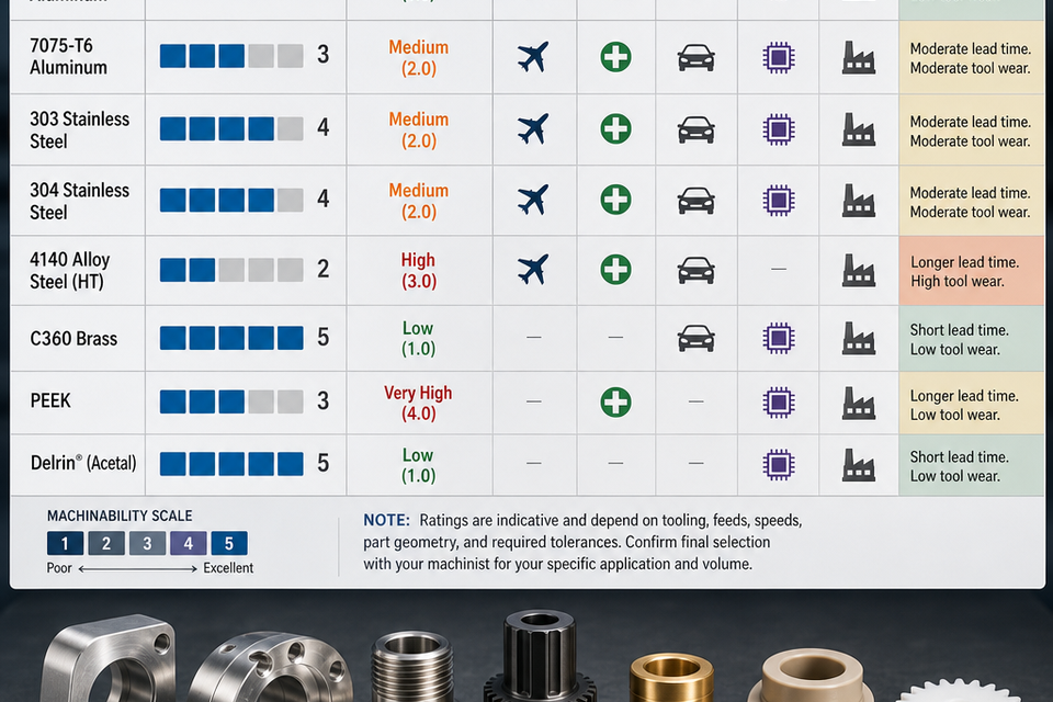
Use this matrix as a starting point: machinability drives cycle time and tool wear, cost reflects both raw stock and machining time, and sector requirements (such as medical biocompatibility or aerospace strength-to-weight) often narrow the field before cost is compared. Ratings are indicative; confirm final selection with your machinist against your specific tolerances and volumes.
Choose the material from the part’s function first. Then test each candidate against machinability, cost, and the sector rules it must meet. Habit, such as always specifying 316 or reusing last job’s alloy, often adds cycle time and tooling cost.
Step 1: Define the load and environment.
- What: List the loads, operating temperature, corrosion exposure, and any contact with food or body tissue.
- Why: This sets the minimum strength and corrosion resistance. Anything above that minimum adds cost without adding function.
- How: Write one sentence per requirement, such as “Carries bearing load, indoor humidity only.”
Step 2: Compare candidates on three points.
- Machinability: How fast the shop can cut, and how quickly tools wear.
- Cost: Raw stock price plus machine time.
- Sector requirements: Certifications and traceability the buyer must receive.
For example, 6061 aluminum suits a general housing. 316 stainless suits a medical or food-contact part. The stainless machines more slowly and wears tooling faster, so the same geometry takes longer and consumes more inserts.
Step 3: Confirm stock with the shop. Ask which grades and bar sizes they keep on hand. Non-stocked grades add lead time, and you pay for that wait.
Common mistake: Specifying a high-strength alloy where a standard alloy meets the load case. The harder material slows every cut and adds no value to the part.
Hypothetical RFQ example
A buyer sends an RFQ for a small housing with a bearing bore, a mating face, and three internal pockets. The drawing has no datum reference frame and no internal corner radius. Three shops quote three different parts:
- Shop A (hypothetical): Assumes sharp internal corners, which need a smaller tool and extra setups. Quotes $48 per part.
- Shop B (hypothetical): Assumes a 3 mm corner radius. Quotes $36 per part.
- Shop C (hypothetical): Uses the bore as primary datum and tightens inspection. Quotes $61 per part.
The buyer cannot compare these quotes. Each shop priced a different part.
Revised drawing fixes:
- Primary datum A on the mating face, secondary datum B on the bore axis.
- Internal corner radius of R3 minimum, called out on the drawing.
- Wall thickness minimum set per material, with the value marked for verification against your target supplier’s published capability sheet.
- Tight tolerance only on the bore and mating face. Standard tolerance elsewhere.
Supplier question sheet:
- Which grades and bar sizes do you stock?
- What internal corner radius do you cut without extra setups?
- What minimum wall thickness do you hold in this material?
- Which datum do you use for bore location?
- What inspection records come with each lot?
Pro tip: Check stocked grades on our CNC machining products page or contact our team before finalizing the material.
Some buyers specify 316 for every part to avoid mix-ups. However, that adds machining time to housings that never need it. Set the rule in the bill of materials instead.
Plan about one to two hours per part family to run this check.
Understand How a Shop Builds Your CNC Quote Line by Line
A CNC quote is a sum of cost drivers: setup, machine time, material, inspection, and finishing. Each driver traces back to a decision on your drawing. When you link each line to that decision, you can challenge it, negotiate it, and compare shops on equal terms.
Step 1: Map each line to a drawing decision
What: List every quote line and the drawing feature behind it.
Why: Setup cost rises with each part orientation the shop needs. Machine time rises with tight tolerances and small tools. Inspection time rises with the number of toleranced features.
How: For each line, ask which dimension, datum, or note drives it.
Hypothetical scenario: Your RFQ covers a small aluminum housing with a Ø22 H7 bearing bore, a mating face with 0.05 mm flatness, and three internal pockets. The drawing names the bore and face but does not set a datum order. It also leaves internal corner radii unspecified.
Three shops quote this drawing. All values below are hypothetical:
| Shop A | Shop B | Shop C |
| Datum read | Face first, bore second | Bore first | Face only |
| Setups | 2 | 3 | 2 |
| Pocket corners | R0.5 assumed | Sharp corners, extra operation | R0.2 assumed |
| Inspection | Bore and face | Bore, face, pockets | None listed |
| Unit price | $412 | $538 | $355 |
Shop C looks cheapest. It skips bore inspection and assumes a corner radius your tooling may not reach. Compare only after you fix the basis.
Step 2: Fix the basis in the drawing
What: Remove the ambiguity that forced each shop to guess.
Why: Shops price what the drawing says. Vague notes move cost risk to you in the form of higher quotes or later rework.
How (hypothetical revisions):
- Datum frame: A = mating face (primary), B = bore axis (secondary), C = side face (tertiary). Name each datum in the feature control frame.
- Internal corners: R0.5 minimum. Verify against your target supplier’s published minimum internal radius.
- Wall thickness: 1.5 mm minimum between pocket and outer wall. Verify against the supplier’s thin-wall limit.
- Tolerances: H7 on the bore and 0.05 mm flatness on the face only. Apply a general tolerance elsewhere. Each extra tight feature adds inspection and possibly a setup.
Step 3: Send a supplier question sheet
- Which datum order did you use for setup?
- How many setups does this price include?
- What internal corner radius did you price?
- Which features appear in the inspection report?
- Are material and finishing separate lines?
Pro tip: Request an itemized quote with setup, machine time, material, inspection, and finishing as separate lines. Then compare line by line, not by total.
Common mistake: Accepting the lowest total without checking tolerances, material, and inspection. Shop C’s price may reflect omitted work, not efficiency.
Pricing context: At 50 pieces, setup spreads over few parts, so it often dominates unit price. At several thousand pieces, machine time dominates. Check which regime your quote falls into before judging the price.
Tradeoff: Tightening one bore from H7 to a finer tolerance may add a setup or inspection step. Ask for that change as a separate line before you accept it.
Effort: Expect about two hours to revise the drawing and build a three-quote comparison sheet.
Risk: Changing datums after RFQ release resets every quote. Send the revised drawing to all shops at once.
For sourcing, review CNC machining options or [request an itemized quote](https://www.wldmachinery.com/contact
Decide Between an In-House CNC Cell and an Outsourced Shop
Build an in-house CNC cell only when your annual volume is high enough that its fixed yearly cost per part beats the outsourced price. Below that break-even point, outsource. Then confirm each shop holds the certifications your sector requires and has open capacity.
Step 1: Calculate break-even volume
- What: Add up the annual in-house cost: machine depreciation, labor, programming, tooling, and floor space. Compare it with the outsourced price per part.
- Why: Fixed costs stay the same whether you make 500 parts or 5,000. Volume alone drives the cost per piece.
- How: Use this formula with your own numbers:
Break-even volume = annual fixed in-house cost ÷ (outsourced price per part − in-house variable cost per part)
Hypothetical example: fixed cost of $60,000 per year, outsourced price of $16 per part, and in-house variable cost of $4 per part. Break-even is 60,000 ÷ (16 − 4) = 5,000 parts per year. Below 5,000, outsourcing costs less.
Common mistake: Ignoring utilization. The $60,000 assumes the cell runs close to its planned hours. A cell at 30 percent utilization carries the same fixed cost with a fraction of the output, so your real cost per part can exceed three times the planned figure.
Step 2: Check certifications and capacity
- What: Confirm the shop holds the certifications your sector requires, such as AS9100 for aerospace or ISO 13485 for medical devices. Confirm it has machine hours free for your schedule.
- Why: A shop without the right certification cannot supply some sectors, whatever its price.
- How: Request a copy of the current certificate and its scope. Ask what share of machine hours are already booked.
Step 3: Screen shops with a clear drawing
A hypothetical RFQ shows why drawing clarity matters. The package covers a small aluminum housing with a bearing bore, a mating face, and three internal pockets. It names a datum on the mating face but never defines the bore’s datum role, and it gives no internal corner radius. Three hypothetical shops quote three interpretations:
- Shop A (hypothetical): Datums from the mating face, uses a 3 mm end mill, quotes $38 per part.
- Shop B (hypothetical): Assumes sharp corners, switches pockets to EDM, quotes $71 per part.
- Shop C (hypothetical): Datums from the bore centerline, uses a 1 mm corner radius, quotes $52 per part.
The spread comes from the drawing, not from the shops. A revised drawing (all values hypothetical) fixes it:
- Primary datum A: Mating face. Secondary datum B: B
Conclusion
The strongest article here is the one that stays practical: define the scope clearly, show the tradeoffs, and help the reader choose the next action with confidence.
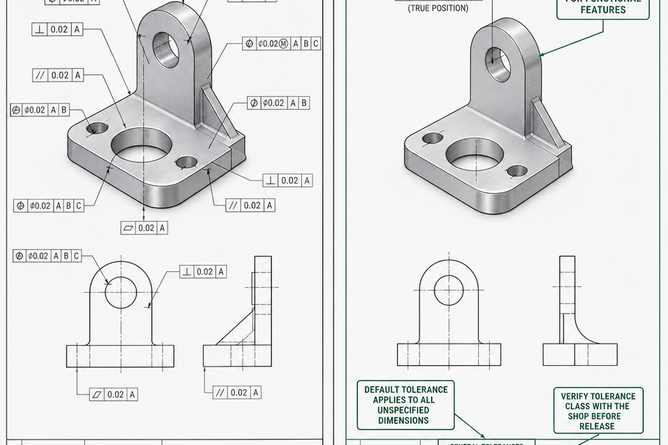
Set the general-tolerance block first. Every unspecified dimension then inherits a known tolerance, and GD&T is reserved for the few features that control fit or function. This keeps drawings cheaper to quote and easier for the machine shop to inspect.
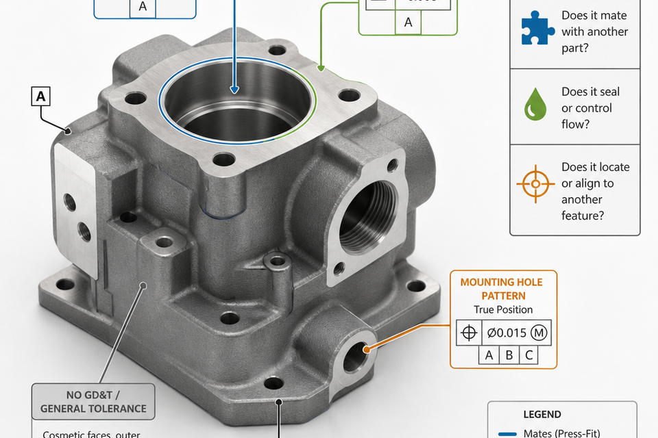
Apply GD&T only where a feature mates, seals, or locates. Callouts on cosmetic or non-functional surfaces add inspection cost and drive scrap without improving fit or function, and they can obscure the tolerances that actually matter.