For buckets treated as CNC machining complex parts, production readiness depends on more than confirming the overall bucket shape. OEM buyers should first lock the application condition, bucket type, carrier or mating interface, pin and lug geometry, wear and reinforcement zones, cutting-edge or attachment interfaces, drawing revision, welding scope, post-fabrication machining points, inspection plan and sample-approval criteria. The highest-risk features are usually the relationships between welded structure and machined mounting interfaces. If ear positions, pin-bores, center distances or wear details are not controlled before production, a bucket can look correct yet require assembly rework or fail to match the customer’s intended duty.
Why Bucket Structural Parts Are Complex CNC Machining Projects
A bucket is primarily a welded structural component, but many bucket projects also contain machined features that determine whether the assembly fits the carrier, linkage, pins, bushings or attachments. Those interfaces turn the project into a combined fabrication-and-machining problem rather than a simple plate-welding job.
The complexity comes from interaction. Welding can influence the position of lugs and ears. Reinforcement can change local stiffness and affect distortion. Machining can correct or establish final interface geometry, but only if enough material and a suitable datum strategy remain after fabrication. Wear components may protect the bucket in service while also changing weight, clearance or maintenance access.
For this reason, the production route should follow the final assembly requirement:
application condition → bucket configuration → mounting geometry → welded structure → finish-machined interfaces → inspection → production approval.
WLD’s Construction Machinery category includes structural components for OEM projects. A bucket order becomes production-ready only when the buyer’s actual interface and operating conditions are translated into a controlled drawing package.
What Application Conditions Should Buyers Confirm First?
Bucket design and manufacturing checks should begin with the work the bucket is expected to perform. The same general bucket envelope may be unsuitable across excavation, loading, trenching, rock handling, loose material or other duties because the force path and wear pattern can change.
The RFQ should describe the equipment and application without relying on a product name alone. Useful inputs include:
- machine or carrier model, where the project is tied to a specific interface;
- bucket type or intended function;
- material being handled;
- material density where it affects load and capacity selection;
- abrasion, impact and digging severity;
- working environment, including rock, soil, aggregate, scrap or other media;
- target bucket capacity or envelope if controlled by the OEM design;
- existing coupler, linkage or pin interface;
- replaceable wear-part or cutting-edge strategy if already specified.
These conditions influence which areas need reinforcement and which dimensions must remain compact. A heavy wear package may improve protection in an abrasive duty but can also add mass or reduce internal volume. A bucket intended for a particular quick coupler may require tighter control of mounting geometry than a generic pin-on design.
| Application Condition |
Bucket Design Consideration |
RFQ Input |
| Abrasive material |
Wear protection may be concentrated at cutting, side and bottom contact zones |
Describe material and expected wear severity |
| High-impact digging |
Load paths and reinforcement become more critical |
State duty and OEM structural requirements |
| Restricted machine interface |
Lug, pin, coupler and clearance geometry control fit |
Provide mating-interface drawing |
| Capacity-sensitive duty |
Reinforcement and wear additions may affect internal envelope |
Freeze required bucket envelope or capacity from OEM design |
| Replaceable wear system |
Attachment locations and service access must be controlled |
Provide approved wear-part interface details |
Which Mounting and Interface Dimensions Affect Assembly?
The mounting interface is usually the first place to look when a bucket reaches the assembly line but will not fit. The buyer should identify all dimensions that control the relationship between the bucket and its carrier or linkage.
Depending on the bucket architecture, critical features may include pin-hole diameter, center distance between pin bores, spacing between mounting ears, lug thickness, bore alignment, bushing seats, coupler contact surfaces, stop positions and clearance to the linkage. These are common engineering examples; the approved customer drawing must decide which of them apply to the actual bucket.
Relationships matter more than isolated measurements. Two pin bores can each be within diameter tolerance but still fail assembly if their center distance, coaxial relationship or position to the bucket centerline is wrong. Likewise, ear spacing may be correct before welding but change after the surrounding structure is completed.
The manufacturing plan should therefore identify which interfaces are established by welding fixtures and which are finish-machined after fabrication. If pin bores or mating surfaces are machined in the completed weldment, the supplier should reference the drawing datum used to locate them.
A pre-production drawing review should highlight these features explicitly. The buyer can then require the first-article report to show the dimensions that prove interface compatibility rather than receiving a long report filled mainly with noncritical dimensions.
How Do Wear Areas and Reinforcement Details Affect Production?
Wear protection is part of the structural design, not a decorative add-on. Cutting edges, side plates, heel areas, bottom surfaces, wear strips, shrouds or other protection can change the load path, welding sequence, dimensional stability and final weight of the bucket.
The buyer should freeze where wear components are located, whether they are welded or mechanically attached, which surfaces must remain accessible, and whether worn components are intended to be replaceable. If the wear package is not finalized before sample production, later changes can force new plate preparation, new weld layouts or renewed dimensional approval.
Reinforcement should also be reviewed against the application. Adding more plate is not automatically safer. Uncontrolled reinforcement can create local stiffness changes, interfere with adjacent components, reduce clearances or change the internal bucket geometry. The approved design should define the reinforcement rather than leaving the factory to “make it stronger” based on general experience.
For CNC-machined complex parts, reinforcement can also affect machining access. A rib or gusset added close to a pin bore may obstruct the machining setup or inspection access. This is why wear and reinforcement layout should be frozen before the supplier commits to tooling and production routing.
What Drawing Version and Technical Documents Should Be Locked?
Bucket projects often involve multiple files: a 3D model, assembly drawing, plate drawings, wear-part details, interface drawings and perhaps customer-supplied components. Production should not begin until these files are controlled as one revision package.
The technical release should define:
- controlling 2D assembly drawing and revision;
- supporting 3D model revision;
- bill of materials or component list where provided;
- material specifications;
- weld symbols and any project-specific weld requirements;
- machined features, datums and tolerances;
- pin, bushing, coupler or wear-part interface drawings;
- surface-treatment requirements where applicable;
- approved substitutions or no-substitution rules;
- inspection characteristics and sample-approval requirements.
The purchase order should reference the same revision used for quotation. If a drawing changes after the supplier has planned fixtures or begun cutting, the buyer and supplier need a formal change review covering affected material, tooling, work-in-process and inspection documents.
Revision discipline prevents a subtle but common production problem: a supplier manufactures to the newest 3D file while the buyer inspects against an older 2D drawing, or vice versa. The documents may look similar but contain a changed lug position, plate profile or wear feature that affects assembly.
Which Machining and Welding Checkpoints Should Be Discussed Before Production?
For bucket structural parts, the buyer does not need to prescribe every welding pass or machine setup. However, the supplier should explain how the proposed route protects drawing-controlled interfaces.
Useful pre-production checkpoints include:
- which subassemblies are welded before the mounting ears are fully fixed;
- whether fit-critical bores or faces are machined before or after major welding;
- how the supplier establishes the final datum for interface machining;
- whether machining allowance is required at critical interfaces;
- how weld distortion is considered before final dimensional inspection;
- which wear parts are installed before or after interface machining;
- which features are inspected before they become hidden by later assembly;
- which deviations require buyer approval.
This is where “CNC machining parts” and “welded structural parts” stop being separate purchasing categories. The bucket’s mounting geometry may depend on machining, but that geometry is created within a welded structure whose distortion and sequence also matter.
A strong supplier response should show that the fabrication and machining plans are connected. A quote that lists welding and machining as two independent operations without explaining their interface may still leave production risk unresolved.
Which Inspection Points Should Be Discussed Before Production?
The inspection plan should be built around assembly risk, wear-related geometry and drawing-defined acceptance. It should not be a generic promise that “all dimensions will be checked.”
| Production Check |
Why It Matters |
Buyer Verification |
| Mounting interface |
Controls fit to carrier, linkage or coupler |
First-article dimensions referenced to approved datums |
| Pin bores and related centers |
Incorrect relationship can prevent assembly even if individual diameters are correct |
Verify bore size, position and relationship required by drawing |
| Ear/lug spacing |
Weld distortion can alter final fit |
Inspect in finished or agreed production condition |
| Bucket envelope |
Controls clearance, capacity envelope and logistics fit |
Check approved overall and functional dimensions |
| Wear/reinforcement location |
Wrong placement can interfere with mating parts or reduce service access |
Compare against drawing and approved sample |
| Welded structure |
Fabrication errors can create distortion or missing structural details |
Visual/dimensional inspection and any project-specified weld acceptance |
| Revision identity |
Correct part made to wrong revision still fails the order |
Drawing revision shown on inspection and shipping documents |
If the project requires special testing, nondestructive examination, material certificates or a particular inspection standard, those requirements should be stated in the drawing or purchase specification. They should not be assumed from the phrase “heavy-duty bucket.”
RFQ Inputs for Various Types Buckets and Structural Parts
A useful RFQ allows the supplier to evaluate both the bucket design and the production route. Include:
- bucket type and application;
- machine, carrier or coupler interface;
- material being handled and severity of service;
- controlled bucket capacity or envelope if specified by the OEM;
- approved 2D drawing and revision;
- supporting 3D model;
- material and component specifications;
- mounting ear, pin and bore interfaces;
- wear-part and reinforcement layout;
- welding scope;
- features requiring CNC machining;
- critical datums and tolerances;
- included pins, bushings, adapters or wear components if any;
- surface treatment requirements;
- first-article and inspection requirements;
- deviation and engineering-change process;
- quantity and expected production stage;
- identification, packaging and delivery requirements.
Ask the supplier to identify any missing interface dimension or unclear scope before issuing the final quotation. This is especially important for custom CNC machining complex parts because a supplier can only plan machining fixtures, weld sequence and inspection around geometry that has actually been released.
Final Production Readiness Checklist for Buyers
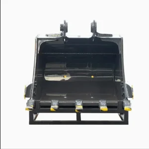
Production readiness is reached when the buyer and supplier are working from the same technical baseline and the fit-critical features have a defined verification path. Before authorizing material cutting or batch production, confirm that:
- the application and bucket type are frozen;
- the mating interface is defined by an approved drawing;
- all pin, bore, ear and coupler relationships required for assembly are controlled;
- wear and reinforcement details are no longer provisional;
- the controlling drawing and model revisions match;
- fabrication and CNC machining scopes are clearly separated and complete;
- the supplier has declared process assumptions and proposed deviations;
- first-article inspection covers the features that determine fit;
- special inspection or testing requirements are stated rather than assumed;
- the approved sample/drawing revision will control repeat production;
- packaging protects interfaces and identifies the correct part revision.
The Various Types Buckets page is the target WLD product reference for this topic. WLD’s current client data supports its OEM structural-component positioning and drawing-based customization for construction machinery, but it does not establish a specific bucket material, plate thickness, capacity, welding standard, tolerance capability, test report, lead time or production volume. Those details should be supplied by the buyer’s design or confirmed in the project quotation.
Once the mounting geometry, wear layout, revision and inspection plan are frozen, OEM buyers can send the released package through WLD’s contact and RFQ page for production review and quotation.