The right CNC machining setup for a mining weldment is the one that can hold its functional interfaces in the correct relationship after welding, handling, machining, and inspection. Buyers should therefore evaluate more than axis count or machine size. The decision must account for the weldment envelope and mass, machine travel and load capacity, datum strategy, fixture access, tool reach, the number of setups, machining sequence, and the measurement method used for final acceptance. A machine may physically accommodate the part yet still be a poor choice if it cannot reach critical faces without unstable extensions or repeated datum transfers.
Why machine size alone does not answer the selection question
Large mining structures often combine welded plates, ribs, brackets, bores, pads, and mounting faces. These features do not all carry the same functional importance. A buyer may care most about the relationship between a mounting face and a bore centerline, the position of a hole pattern relative to an assembly datum, or the flatness of an interface that transfers load into another structure. The machining setup must protect these relationships, not simply remove material from every accessible surface.
That distinction changes how quotations should be compared. Two suppliers may both propose machines with sufficient nominal travel, but one route may require three datum transfers while another holds the main interfaces in one controlled setup. The second route is not automatically better or cheaper; it may demand a larger fixture, more complex probing, or longer machine occupancy. The buyer needs to understand the complete process logic behind the quotation.
Start with the interfaces that control assembly
A sound selection process begins with the released drawing and the mating assembly. Buyers and suppliers should identify which surfaces, bores, hole patterns, and centerlines establish the part in the finished machine. These become the basis for the datum and fixture discussion. Features that are visually prominent may be less important than a small machined pad that controls the position of a cylinder bracket or bearing housing.
The drawing should communicate design intent through a consistent dimensioning and tolerancing scheme. A datum is not simply a convenient edge from which an operator takes measurements. It represents the reference framework used to orient and locate features. If the proposed machining datum is an unstable as-welded surface, variation in that surface can be transferred into every later operation.
Before requesting a final quote, the buyer should identify:
- the assembly interfaces that affect fit, alignment, movement, sealing, or load transfer;
- the drawing revision and any approved deviations;
- the datum features and the order in which they establish the reference frame;
- features that must be machined in a common setup or verified as a related group;
- surfaces that may remain as welded, flame-cut, or otherwise unfinished;
- the party responsible for machining allowance and weld-distortion compensation.
This information lets the supplier propose a machine and route around the component’s function instead of choosing equipment from overall dimensions alone.
Match the machine configuration to the real cutting envelope
The part envelope is only the starting point. The usable cutting envelope must include fixtures, clamps, tool holders, spindle access, rotary movement where applicable, and clearance for probing or measurement. A tall weldment can fit inside a machine but block the spindle from reaching an internal pad. A long tool can reach the pad yet introduce rigidity and surface-finish risks. Rotating the part may solve access but create a new lifting, support, and datum-transfer problem.
Buyers should ask the supplier to explain the proposed orientation for each important operation. A simple setup sketch can reveal more than a list of machine specifications. It should show where the part is supported, how it is restrained, which features are machined first, what must be repositioned, and how the reference frame is recovered after each move.
| Selection variable | Question for the supplier | Why it matters |
| Usable travel and table load | Does the quoted capacity include the fixture, supports, and safe clearance? | Nominal machine capacity may not equal the usable process window. |
| Spindle orientation and access | Can the tool reach every critical face and bore without excessive extension? | Access affects rigidity, accuracy, cycle time, and surface condition. |
| Number of setups | Which datum relationships are preserved after repositioning? | Every transfer creates another opportunity for location error. |
| Fixture and support plan | Where is the weldment supported, clamped, and allowed to settle? | Thin plates and long spans can deflect under clamping or cutting loads. |
| Measurement access | Can the agreed features be measured in the proposed orientation? | A process is incomplete if acceptance cannot be demonstrated. |
For OEM teams sourcing structures across the mining equipment component range, the useful question is not “Do you have a large CNC machine?” It is “How will this drawing be located, supported, machined, and verified without losing the functional datum relationships?”
Control welding and machining as one connected process
Welding creates local heat input, shrinkage, and residual stress. Machining then removes material that may have helped balance the structure. For a large fabricated component, the condition measured immediately after welding may not be the condition that remains after rough machining, repositioning, or final release from the fixture. This is why a machining route should not be reviewed in isolation from fabrication.
There is no universal sequence that fits every mining weldment. Depending on the design and material requirements, the agreed route may include fabrication, dimensional checking, an intermediate treatment or stabilization step when specified, rough machining, a controlled interval or recheck, and final machining. Buyers should not impose a generic stress-relief requirement without considering the drawing, material, welding procedure, and engineering intent. They should require the supplier to state the proposed sequence and identify where distortion is expected to be checked.
Machining allowance also needs an owner. If the fabrication drawing does not state how much stock remains on critical pads, the welder and machinist may make different assumptions. Too little allowance can leave an interrupted or incomplete finished surface after distortion. Excessive allowance increases cutting time and can cause additional movement when material is removed. The supplier’s route should connect allowance, weld sequence, fixture support, and final tolerance.
Choose datum transfers deliberately
One-setup machining is attractive because it reduces transfers, but it is not a universal requirement. Some structures cannot be accessed safely or efficiently in one orientation. The practical goal is to minimize unnecessary transfers and make every necessary transfer recoverable and measurable.
For a multi-setup route, buyers should look for stable reference features, protected locating surfaces, a defined probing or alignment method, and an inspection plan that checks relationships across setups. Temporary or sacrificial datum pads may be useful when they are part of the approved process, but they should not be added to a controlled design without agreement. The same applies to tack-on lifting points, machining lugs, or fixture tabs.
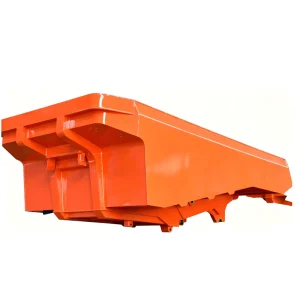
A representative mining truck body weldment illustrates the planning challenge: a large fabricated body may combine broad plate structures with localized interfaces that must connect to the vehicle assembly. The relevant machining decision is therefore driven by those interfaces and their accessibility, not by the visible size of the body alone.
Do not treat axis count as a quality grade
More axes can improve access and reduce repositioning for some geometries, but axis count is not a standalone measure of process capability. A rigid three-axis or boring-mill setup with a well-designed fixture may be more stable for certain long bores or planar interfaces than a more complex arrangement. Conversely, indexed or simultaneous rotary movement can be valuable when angled features or multiple faces must remain related.
The buyer should compare process risk rather than marketing labels. Key questions include whether the machine can carry the combined load, whether the spindle remains rigid at the required reach, whether the fixture supports the structure near cutting zones, whether chip evacuation and tool access are practical, and whether the operator can re-establish the agreed datum system after any rotation or transfer.
A credible supplier response explains why the proposed configuration fits the part. It does not merely provide a machine model, a maximum travel figure, or a photo of a large shop floor.
Build inspection into the setup decision
Inspection should be planned before cutting starts. The drawing may require relationships that cannot be verified reliably with a tape, straightedge, or isolated hand-gauge reading. Large components may need a combination of in-process probing, conventional gauges, portable coordinate measurement, laser tracking, or another suitable method. The correct method depends on the feature, tolerance, accessibility, environmental conditions, and agreed acceptance criteria.
For critical interfaces, ask how the supplier will establish the inspection datum, which actual values will be recorded, and how measurement equipment status will be identified. A report that says only “PASS” provides less diagnostic value than a report showing the measured result, feature identification, datum setup, instrument or method, and drawing revision. The buyer should also confirm whether inspection occurs while the part is clamped, after release, or at both stages where movement is a concern.
This evidence closes the loop between design intent and manufacturing. If the measurement plan cannot reproduce the same reference framework used for machining and assembly, apparent compliance at individual features may still hide a relationship problem.
Plan the first article before approving repeat production
A new or revised mining weldment should establish a repeatable route before the buyer assumes that later batches will behave the same way. The first article is an opportunity to confirm datum accessibility, fixture reaction, stock allowance, tool reach, inspection coverage, handling steps, and document format. It is not only a final dimensional check.
When the first part reveals a necessary process adjustment, the change should be reflected in controlled work instructions, fixture references, inspection plans, or drawing feedback as appropriate. Repeat production then depends on the approved route, material and revision traceability, controlled deviations, and consistent acceptance records. Buyers should distinguish a one-time recovery by an experienced machinist from a process that another shift can execute reliably.
What should a useful mining weldment RFQ contain?
A quotation is easier to compare when every supplier receives the same technical boundary. The RFQ package should include the current 2D drawing and 3D model where available, material and welding requirements, expected batch quantity, delivery destination, functional interfaces, datum scheme, machining allowances or responsibility for defining them, acceptance criteria, and required inspection records. It should also identify coating or surface-protection boundaries and any machined faces that must remain protected during transport.
Ask each supplier to return a proposed process route, machine and setup concept, planned datum transfers, fixture approach, major subcontracted processes if any, inspection method, document package, lead-time assumptions, and a list of technical exceptions. This creates a common basis for comparing risk as well as price.
OEM buyers can use WLD’s drawing-based project enquiry form to share the drawing revision, part envelope, approximate mass, batch requirement, functional interfaces, and inspection expectations. A complete enquiry allows the manufacturing team to review whether the proposed fabrication, machining, and verification route fits the application before a production commitment is made.