Direct Answer: A CNC-machined excavator upper frame can pass dimensional inspection yet fail slewing-bearing assembly when the inspection does not reproduce the bearing’s real mounting condition. Typical causes include mounting-face flatness under the wrong support condition, local high spots, bolt-hole position error, datum-axis mismatch, weld distortion, machining-induced stress release, surface contamination, or frame deformation during bolting and transport.
This problem matters to excavator OEMs, construction-machinery manufacturers, structural-component buyers, assembly plants, and quality engineers sourcing welded and machined upper frames. A report may show that every inspected dimension is within its drawing tolerance, yet the slewing bearing still does not seat evenly, bolt holes do not align freely, bolts pull the bearing into position, or rotation becomes tight after assembly. The gap is usually not “inspection versus no inspection.” It is whether the inspection controlled the same functional interfaces that the bearing sees during installation.
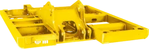
WLD supplies construction machinery structural components, including the Excavator Upper Frame Slewing Platform. For OEM procurement, the release plan should connect welding condition, CNC machining, datum strategy, bearing-interface inspection, handling, and assembly evidence rather than treat each process as an independent pass/fail step.
What Does “Pass Inspection but Fail Assembly” Actually Mean?
Before root-cause analysis, the buyer should define the assembly failure precisely. “The bearing does not fit” can describe several different conditions, each pointing to a different control problem.
| Assembly Symptom | Possible Interface Problem | Evidence to Check First |
| Bearing rocks or does not sit fully on the mounting face | Global flatness, local high spot, weld bead, paint, burr, contamination, or support deformation | Mounting-face map, surface condition, support method during measurement |
| Some bolt holes align while others require forcing | Hole true position, pitch-circle relationship, datum-axis mismatch, frame distortion, bearing orientation | Hole-position report, bearing drawing, datum definition, free-fit assembly check |
| Bolts enter but bearing becomes tight after tightening | Uneven support, frame flexibility, local surface error, bolt-induced distortion | Pre/post-bolting face condition, tightening sequence, bearing rotation check |
| Pinion or gear mesh changes around the circumference | Bearing axis, mounting-plane distortion, gear alignment, structural deflection | Runout/alignment data and assembled gear-backlash checks required by the project |
| Frame passed factory inspection but fails at the OEM line | Different support condition, transport distortion, different datum setup, or incomplete interface inspection | Factory inspection setup versus assembly-line support and handling history |
Industry experience point: The phrase “all dimensions passed” is weak evidence until the buyer knows which dimensions were checked, from which datums, under what support condition, and whether the bearing interface was measured as a functional system.
Why Can Mounting-Face Flatness Pass on the Machine but Fail Under Assembly Conditions?
A large welded upper frame is not an infinitely rigid block. Its measured geometry can change with support points, clamping, residual stress, handling, and the sequence in which machining fixtures are released. A mounting face that appears acceptable while the frame is restrained on a machine table may not remain in the same condition when the part is placed on the OEM’s assembly fixture.
This is particularly important for slewing-bearing mounting surfaces because the bearing relies on broad, continuous support from the companion structure. Local peaks, abrupt changes, or unsupported sectors can force the bearing ring to conform when the bolts are tightened.
Buyers should therefore define:
- how the frame is supported during final interface inspection;
- whether the inspection condition represents the assembly condition;
- which face or datum establishes the bearing mounting plane;
- whether a full circumferential surface map is required rather than a few point checks;
- how the frame is released from machining fixtures before final measurement;
- whether reinspection is required after major rework or transport.
Industry experience point: Measuring only several points around a large ring seat can miss a narrow local high area. A bearing can bridge or be forced across that sector even when the average plane looks acceptable.
How Can Weld Distortion Reappear After CNC Machining?
Machining can make a distorted weldment dimensionally correct at one stage without eliminating the underlying structural tendency to move. If the weldment contains residual stress or has not reached a stable condition before final machining, material removal and fixture release can change the final shape.
The problem is not that CNC machining is inaccurate. The problem is using final machining as the only correction method for an unstable welded structure. If one frame reaches the target plane only because a large amount of material is removed from one sector, the part may have little margin for later stress redistribution or assembly loading.
The OEM should review the complete route from fabrication to machining:
- weld sequence and restraint strategy;
- intermediate dimensional checks;
- condition of the weldment before rough machining;
- machining allowance on the bearing seat;
- any project-required stress-control step;
- rough versus finish machining sequence;
- fixture release before final inspection.
Industry experience point: A final-machined surface can be flat while the surrounding structure remains unstable. Production readiness requires evidence that the welded frame reaches machining in a repeatable condition, not just that one part can be cut back into tolerance.
Why Are Bolt-Hole Position and Bearing-Axis Datums Easy to Misread?
A bolt circle may pass a simple hole-to-hole dimension check while still being shifted, rotated, or eccentric relative to the functional slewing axis. The important question is not whether adjacent hole spacing looks correct; it is whether the complete hole pattern is correctly located relative to the bearing seat and the OEM’s defined datums.
Typical specification gaps include:
- hole pattern controlled from a fabrication center rather than the machined bearing axis;
- separate inspection of hole spacing without true-position relationship to the mounting datum;
- bearing-seat diameter and bolt circle measured in different setups;
- unclear zero-angle or orientation reference;
- drawing revisions that change hole or datum references without updating the inspection program.
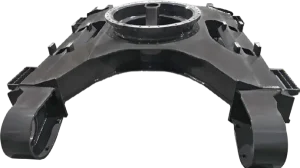
WLD also lists an Excavator Lower Frame, which is part of the same construction-machinery structural-component cluster. Upper- and lower-frame interfaces should still be inspected against their own controlled drawings; the existence of matching product families does not establish interchangeability or assembly tolerances.
| Interface Feature | Weak Inspection Approach | Stronger OEM Control |
| Bearing mounting plane | Check a few heights from an arbitrary base | Map the functional plane from the specified datum under the defined support condition |
| Bolt circle | Check adjacent hole spacing only | Control complete hole position relative to the bearing axis and orientation datum |
| Center opening | Measure diameter only | Verify diameter plus its relationship to the bearing and frame datums |
| Mounting pads / interfaces | Inspect each feature independently | Verify relationships that determine final assembly alignment |
| Final report | List dimensions without setup information | Record drawing revision, datum scheme, support condition and inspection method |
Can Surface Condition Cause Assembly Failure Even When Geometry Is Correct?
Yes. A slewing-bearing seat must be treated as a functional contact surface. Weld spatter, paint build-up, burrs, machining chips, dents, corrosion products, adhesive residue, or other local irregularities can create a high point that changes how the bearing ring is supported when bolts are tightened.
The buyer should define who is responsible for final cleaning and protection of the mounting face, which surfaces may be coated, how machined faces are protected during transport, and what receiving inspection must be completed before the bearing is installed.
Industry experience point: A frame can leave final inspection compliant and arrive at assembly with a damaged bearing seat because a machined face was used as a contact point for chains, blocks, or transport restraints.
Why Can Bolting Turn a Good Fit Into a Tight Bearing?
If the bearing initially sits on the frame but rotation becomes tight after bolting, the assembly process may be revealing a support or stiffness problem. Tightening does not merely “hold the bearing down.” It forces the bearing ring and companion structure into a shared condition.
If the mounting face has uneven support or the frame flexes significantly under the bolt load, the bearing can become distorted after tightening. That is why the buyer should distinguish three checkpoints:
- bearing seats freely before bolts are tightened;
- bolts enter without using them to pull the bearing into alignment;
- the assembled bearing remains within the OEM’s required rotation, alignment, and gear-interface checks after the specified tightening procedure.
The exact bolt preload, tightening sequence, bearing flatness limit, and gear-backlash requirement must come from the approved bearing and machine documentation. They should not be invented by the upper-frame supplier or copied from another excavator model.
Why Does the Inspection Support Condition Matter So Much?
A heavy upper frame may be measured on a machining table, inspection stands, transport supports, or the OEM’s assembly fixture. Those support conditions can load the structure differently. If the drawing defines inspection in a free state or on specified reference supports, both supplier and buyer should use that condition consistently.
Otherwise, two inspection reports can disagree even when both measurement systems are functioning correctly. The dispute is caused by the part being measured in two mechanically different states.
Industry experience point: When a large welded frame “changes dimension” between supplier and customer, the first check should be support points and clamping condition before assuming either measurement system is wrong.
Scenario: The Bearing Fits One Sector but the Last Bolts Will Not Enter
Representative scenario — not a claimed WLD customer case.
Business Background: An excavator OEM receives a CNC-machined upper frame. The final dimensional report shows the machined mounting plane, center opening, and bolt-hole dimensions as accepted.
Problem: During slewing-bearing installation, most bolts enter freely, but the final sector requires the bearing to be shifted and several bolts must be forced into alignment. After tightening, rotation is noticeably tighter than during the initial placement check.
Cause: The supplier’s inspection checked local hole spacing and several mounting-face points but did not verify the complete bolt pattern relative to the functional bearing axis under the production assembly support condition. A local face high spot and small pattern shift combine to distort the bearing when the bolts are tightened.
Solution: The OEM and supplier re-establish the controlled datum scheme, map the complete bearing seat, verify the bolt circle relative to the same functional axis, review support conditions, and perform a free-fit bearing/fixture check before the next batch is released. The inspection report is revised to record setup, datums, and critical interface relationships.
Buyer Decision Value: The buyer avoids treating the symptom as a bearing problem and converts the assembly failure into measurable upper-frame interface controls for repeat production.
What Should the First-Article Inspection Include for the Slewing-Bearing Interface?
The first-article plan should focus on the functional interface, not simply every dimension equally. The OEM should identify which characteristics determine whether the bearing can be installed without forcing and operate in the intended machine geometry.
A project-specific first-article package may include:
- controlled drawing revision;
- bearing-seat flatness or surface-profile evidence required by the drawing or bearing specification;
- bearing-axis and center-opening relationship;
- complete bolt-hole position relative to the functional datums;
- orientation reference or zero-angle feature where applicable;
- surface-condition check of the mounting face;
- critical mounting-pad and frame-interface dimensions;
- inspection support condition and setup record;
- deviation/rework history affecting the bearing interface;
- assembly or functional verification required by the OEM.
For broader pre-quote data control, buyers can review WLD’s large-part CNC machining RFQ guide. For an excavator upper frame, the RFQ should add bearing-interface geometry and assembly evidence that may not be necessary for a generic large machined weldment.
How Should OEM Buyers Separate Measurement Error From Process Error?
| Observed Problem | Check Measurement System | Check Manufacturing / Assembly Process |
| Supplier and OEM flatness results disagree | Datum, support points, temperature, measuring path, instrument setup | Fixture release, transport distortion, local surface damage |
| Bolt holes appear shifted | Coordinate alignment, datum origin, drawing revision | Hole machining setup, weldment movement, wrong orientation reference |
| Bearing rotates freely before bolting, tight after bolting | Pre/post-bolting inspection method | Mounting-face support, frame stiffness, tightening process |
| One batch assembles, next batch does not | Inspection-program revision and fixture verification | Weld variation, process change, fixture wear, unapproved rework |
Buyers should avoid responding to every assembly issue by tightening the part tolerance. If the real cause is an inconsistent datum, support condition, fixture, or inspection method, a tighter drawing tolerance can increase cost without removing the failure mechanism.
Industry experience point: Supplier qualification should evaluate whether the manufacturer understands the functional datum chain and assembly condition, not only whether it owns a large CNC machine.
What Should Be Frozen Before Repeat Production?
Before releasing a batch, the OEM should freeze the bearing-interface drawing revision, critical datums, accepted welding and machining route where buyer-controlled, support condition for final inspection, bearing-seat verification method, hole-position inspection method, first-article evidence, rework approval rules, packaging/protection of machined surfaces, and change-control ownership.
If a prototype or first article required localized weld correction, machining recovery, hole rework, or unusual shimming, that history should be reviewed before it becomes an undocumented production method.
What Should the RFQ Include for a CNC-Machined Excavator Upper Frame?
The RFQ should provide the controlled upper-frame drawing, material requirements, weld requirements defined by the OEM, functional datum system, slewing-bearing drawing or interface specification, mounting-face requirements, bolt pattern and orientation references, critical mounting interfaces, machining boundary, inspection/FAI scope, support condition for measurement, bearing or assembly verification requirements, batch quantity, packaging protection, delivery condition, and change-control rules.
Ask the supplier to identify any assumption that affects the slewing-bearing interface. A quotation should not silently assume how the bearing seat will be measured, how the frame will be supported, or which party owns final assembly verification.
Frequently Asked Questions
Can an excavator upper frame be dimensionally correct and still distort a slewing bearing?
Yes. Individual dimensions can pass while mounting-face support, local flatness, structural stiffness, bolt-hole relationships, or assembly support conditions still force the bearing ring into an unfavorable shape during tightening.
Should bolt holes be checked only by center-to-center spacing?
No. For assembly, the complete pattern should be controlled relative to the functional bearing axis and drawing datums. Correct local spacing does not prove the entire pattern is correctly located.
Why can the frame measure differently at the supplier and OEM?
Large welded structures can respond to different support, clamping, handling, and temperature conditions. Both parties should compare the measurement setup and support condition before concluding that one report is wrong.
Should the bearing be used to pull misaligned holes into position?
The project assembly procedure should govern installation, but bolt force should not be used as a substitute for unresolved geometric compatibility. Forced alignment can introduce unwanted stress into the bearing and companion structure.
Can transport damage affect the machined slewing-bearing seat?
Yes. Contact from chains, blocks, straps, metal-to-metal stacking, impact, or inadequate surface protection can damage a compliant machined face after final inspection.
Does a tighter flatness tolerance automatically solve assembly problems?
No. The correct bearing-interface requirement must come from the approved machine and bearing design. Datum definition, support condition, local surface form, stiffness, hole position, and assembly procedure can be as important as the numerical tolerance.
What should buyers send WLD for an excavator upper-frame review?
Send the controlled frame drawing, bearing interface specification, functional datums, material and weld requirements, machining boundary, bearing-seat and bolt-pattern inspection requirements, FAI scope, support condition, quantity, packaging, and assembly feedback.
Request an Excavator Upper-Frame Interface Review
If an upper frame passes dimensional inspection but creates slewing-bearing assembly problems, send WLD the controlled drawing, bearing/interface drawing, datum definition, mounting-face inspection data, bolt-pattern report, assembly symptom, support condition, rework history, batch quantity, and packaging requirements through the Contact page. WLD can review the structural-component and machining scope against the buyer’s defined interface requirements and identify which production or inspection inputs need clarification before a repeat quotation or batch release.